
Table of Contents
Public EV Charging Stations: Network Architecture, Costs & Monetization
The global transition to zero-emission electric mobility depends on a reliable, accessible, and fast network of public EV charging stations. As consumer and commercial EV adoption accelerates globally, public charging networks are evolving from secondary conveniences into critical, high-capacity utility infrastructure.
Deploying public charging infrastructure requires coordinating several core engineering disciplines: high-voltage electrical engineering, civil engineering, telecommunications, and software orchestration.
Public charging sites serve distinct driver needs:
- Destination Charging: Lower-power AC Level 2 or compact DC stations where vehicles dwell for hours (retail centers, hotels, workplaces).
- Highway Corridor Fast Charging: Ultra-high-power DC fast charging (DCFC) hubs providing rapid charges (15–20 minutes) along major transit corridors.
This guide explores site selection, electrical grid design, hardware selection, software protocols, regulatory compliance, and monetization strategies for buildouts.
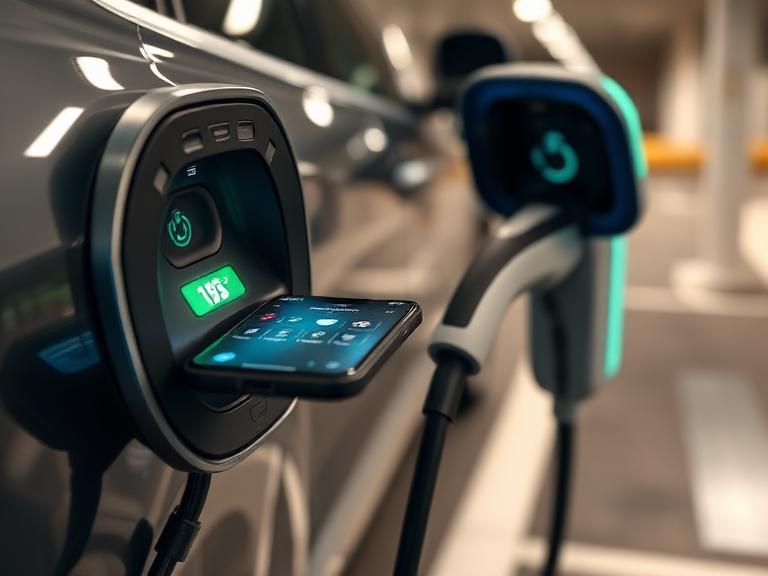
Architectural Classification: Public Charging Categories
Building a viable public EV network requires selecting the appropriate charger speed and hardware profile based on driver dwell times and site constraints.
       Level 2 AC Public               Mid-Tier DC Fast (DCFC)         Ultra-Fast DCFC / Megawatt
   [ 7.2 kW - 19.2 kW Output ]        [ 50 kW - 150 kW Output ]       [ 200 kW - 350+ kW Output ]
   +-------------------------+        +-----------------------+       +---------------------------+
   | Dwell Time: 2 to 6 Hrs  |        | Dwell Time: 30-60 Min |       | Dwell Time: 12 to 25 Min  |
   | Retail, Hotels, Curbside|        | Urban Depots, Malls   |       | Highway Corridors, Fleets |
   +-------------------------+        +-----------------------+       +---------------------------+
| Deployment Tier | Electrical Input | Voltage / Amperage Output | Power Rating (kW) | Primary Dwell Profile | Typical Location Types |
| Public Level 2 AC | 208V/240V 1-Phase | Up to 80A AC | 7.2 kW – 19.2 kW | 2 – 8 Hours | Municipal lots, hotels, parking garages |
| Urban DC Fast (DCFC) | 480V 3-Phase | Up to 150A DC | 30 kW – 90 kW | 45 – 90 Minutes | Supermarkets, urban plazas, quick-serve retail |
| Highway Corridor DCFC | 480V 3-Phase | Up to 500A DC | 150 kW – 350 kW | 15 – 30 Minutes | Highway rest stops, interstates, travel plazas |
| Megawatt Charging (MCS) | High-Volt 3-Phase | Up to 1250A DC | 1,000 kW+ (1 MW+) | 10 – 20 Minutes | Heavy-duty commercial freight hubs |
1. Public Level 2 AC Stations
Public Level 2 chargers use 208V/240V single-phase alternating current to supply power directly to the vehicle’s onboard converter. These units deliver between 7.2 kW and 19.2 kW. They are cost-effective to purchase and install, making them ideal for locations where drivers park for several hours, such as commuter rail hubs, long-term airport parking, overnight hospitality sites, and mixed-use commercial developments.
2. High-Power DC Fast Chargers (DCFC)
DC Fast Chargers bypass the car’s internal AC converter, delivering regulated high-voltage Direct Current straight to the traction battery. Ultra-fast DC dispensers delivering 150 kW to 350+ kW require liquid-cooled cables to handle continuous currents up to 500 amps without overheating. These chargers are vital for highway corridors, enabling drivers to add 150 to 250 miles of range in roughly 15 minutes.
Technical Engineering, Site Selection, & Grid Engineering
Successful deployment of public charging stations requires rigorous site planning and electrical load engineering.
+------------------------------------------------------------------------------------+
|                         PUBLIC SITE SELECTION & ENGINEERING FEASIBILITY            |
+------------------------------------------------------------------------------------+
|                                                                                    |
|  [Step 1: Traffic Analysis] ---> [Step 2: Capacity Assessment] ---> [Step 3: Site Design] |
|  - Daily Vehicle Counts          - Local Substation Feeder Feasibility - ADA Access Routes|
|  - Dwell Time Profiling          - Transformer Step-Down Needs         - Steel Bollard Safety|
|                                                                             |      |
|                                                                             v      |
|  [Step 6: Network Online]   <--- [Step 5: Civil Engineering]  <--- [Step 4: Permitting]  |
|  - OCPP Backend Binding          - Directional Boring                  - AHJ Plan Approval|
|  - POS Payment Testing           - Concrete Pad Foundation             - Utility Inspection|
|                                                                                    |
+------------------------------------------------------------------------------------+
Site Assessment Criteria
Selecting a high-yielding site involves evaluating five main factors:
- Vehicle Traffic & Accessibility: Daily Traffic Counts (AADT) and proximity to major highway exit ramps or high-density urban corridors.
- Proximity to Amenities: Co-location with 24/7 restrooms, food retail, indoor dining, and safe lighting to enhance dwell comfort.
- Electrical Capacity: Distance to the nearest 3-phase medium-voltage distribution line and available utility feeder capacity.
- Physical Footprint & Expansion: Sufficient space for vehicle turning radiuses, pull-through commercial stalls, accessibility aisles, and future cabinet additions.
- Site Visibility & Lighting: Unobstructed visibility from major thoroughfares and clear overhead canopy illumination for nighttime driver safety.
Calculating Electrical Infrastructure Needs
Public DC fast-charging hubs place heavy demands on local electrical grids. A public site featuring four 150 kW DCFC dispensers operating simultaneously requires a minimum site service capacity of 600 kW, plus auxiliary lighting and cooling loads.
$$\text{Total Site Power Demand (kVA)} = \frac{\sum P_{\text{dispensers}} \times \text{Diversity Factor}}{\text{Power Factor} \times \text{Efficiency}}$$
Where:
- $P_{\text{dispensers}} =$ Peak output capacity sum of all installed charging ports
- $\text{Diversity Factor} =$ Coincidence ratio of simultaneous usage (typically $0.85$ to $1.0$ for high-utilization public sites)
- $\text{Power Factor} =$ Inverter power factor (typically $\ge 0.98$ for modern active PFC rectifiers)
- $\text{Efficiency} =$ Inverter conversion efficiency ($\approx 0.95$)
             TYPICAL DC FAST CHARGER HUB DISTRIBUTION SCHEMATIC
+---------------------------------------------------------------------------+
| Utility Primary Feed (12.47 kV 3-Phase)                                    |
+---------------------------------------------------------------------------+
                                     |
                                     v
+---------------------------------------------------------------------------+
| Step-Down Utility Transformer (12.47 kV to 480V 3-Phase)                  |
+---------------------------------------------------------------------------+
                                     |
                                     v
+---------------------------------------------------------------------------+
| Main Service Panel & Distribution Switchboard (2000A, 480V)               |
+---------------------------------------------------------------------------+
                                     |
          +--------------------------+--------------------------+
          |                                                     |
          v                                                     v
+-----------------------------------+                 +---------------------+
| Power Conversion Cabinet (300 kW) |                 | BESS Battery Buffer |
+-----------------------------------+                 +---------------------+
          |                                                     |
    +-----+-----+                                               |
    |           |                                               |
    v           v                                               v
+-------+   +-------+                                 +---------------------+
| Stall |   | Stall | <------------------------------ | Dynamic Power Router|
|   1   |   |   2   |                                 +---------------------+
+-------+   +-------+
When local utility capacity is constrained, developers often install Battery Energy Storage Systems (BESS). BESS units store energy continuously during low-demand periods and release high-power discharge during charging sessions, reducing grid interconnection requirements and mitigating high demand charges.
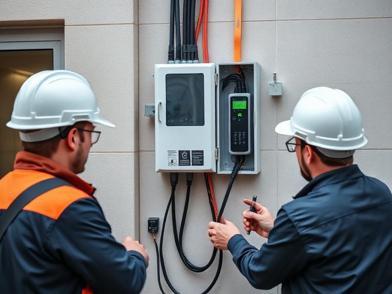
Hardware Connectors and Standard Interoperability
Public charging stations must support multiple vehicle models and connector types to maximize utilization.
  North American Charging Standard (NACS)        Combined Charging System (CCS1)
+---------------------------------------+       +---------------------------------------+
|  Integrated AC/DC High-Power Pins     |       |  J1772 AC Plug + Dual DC High-Current |
|  Lightweight, Compact Footprint       |       |  Bulkier Modular Latch System         |
|  Supports up to 1000V DC / 500A+      |       |  Supports up to 1000V DC / 500A       |
+---------------------------------------+       +---------------------------------------+
| Connector Standard | Primary Regions | Max Voltage / Amperage | Current Market Status |
| NACS (SAE J3400) | North America | 1000V DC / 500A+ | Dominant standard across North American public networks |
| CCS Combo 1 (CCS1) | North America, Korea | 1000V DC / 500A | Legacy standard; widely deployed across existing sites |
| CCS Combo 2 (CCS2) | Europe, Asia-Pacific, SA | 1000V DC / 500A | Regional standard across European and international markets |
| CHAdeMO | Japan (Global Legacy) | 500V DC / 125A–200A | Phasing out; limited to legacy vehicle support |
| GB/T Standard | China | 1000V DC / 250A–500A | Dominant standard in China |
Multi-Standard Dispensers & Cable Management
Modern public charging stalls use dual-connector configurations (NACS + CCS1/2) or integrated passive mechanical adapters to accommodate all incoming EVs. Heavy liquid-cooled charging cables require overhead spring-loaded cable management systems. These systems keep heavy cables off the ground, preventing damage from vehicles running over them, reducing cable wear, and keeping the site accessible and tidy.
Public EV Network Software, Protocols, and Telecom Infrastructure
Public EV charging networks rely on a robust software stack to manage payments, monitor system health, and orchestrate power distribution.
+------------------------------------------------------------------------------------+
|                         PUBLIC NETWORK SOFTWARE PROTOCOL STACK                     |
+------------------------------------------------------------------------------------+
|                                                                                    |
|  [User App / Vehicle]  <--->  [ISO 15118]   <--->  [Charging Dispenser Controller] |
|  - Plug & Charge Auth         Authen / Encryption    - Real-time Telemetry         |
|                                                               |                    |
|                                                               v                    |
|  [Payment Processor]   <--->  [OCPI 2.2.1]   <--->  [OCPP 2.0.1 Central Cloud]   |
|  - Credit Card / NFC          Network Roaming         - Load Management & Billing  |
|                                                                                    |
+------------------------------------------------------------------------------------+
Essential Protocols & Communication Layers
1. OCPP (Open Charge Point Protocol)
OCPP establishes standard communication between physical charging stalls and cloud backends.
- OCPP 1.6J: Widely used protocol supporting basic remote start/stop, smart charging profiles, status notifications, and diagnostic logs.
- OCPP 2.0.1: Modern standard with advanced security (ISO 15118 support), enhanced display management, granular device monitoring, and expanded smart charging options.
2. OCPI (Open Charge Point Interface)
OCPI enables roaming between different charging networks. Drivers can locate, reserve, and pay for charging sessions across different provider networks using a single preferred mobile app or navigation system.
3. ISO 15118 (Plug & Charge)
ISO 15118 enables secure cryptographic authentication directly between the electric vehicle and the charger dispenser. When plugged in, the vehicle securely transmits its billing credentials, automatically initiating charging and processing payment without requiring mobile apps, RFID tags, or credit card swipes.
Site Safety, Physical Design, & Accessibility Requirements
Public infrastructure must be designed for maximum durability, security, and accessibility.
                  PUBLIC DISPENSER ACCESSIBILITY & SAFETY LAYOUT
+-----------------------------------------------------------------------------------+
|                                                                                   |
|    +-------------------+    +------------------------+    +------------------+    |
|    | Steel Bollards    |    | Public Dispenser Unit  |    | Concrete Pad     |    |
|    | (High-Impact Guard|    | (NACS/CCS / Touch POS) |    | (18" Elevation)  |    |
|    +-------------------+    +------------------------+    +------------------+    |
|             |                            |                         |              |
|             v                            v                         v              |
|   =============================================================================   |
|   | [ADA Access Route]  |  5 ft Van-Accessible Aisle | Drive-In Parking Space|    |
|   =============================================================================   |
|                                                                                   |
+-----------------------------------------------------------------------------------+
ADA Compliance Essentials
Public stations must be fully accessible to all drivers:
- Operable Parts Height: Touchscreens, credit card readers, and plug connectors must be mounted between 15 inches and 48 inches from the ground.
- Clear Floor Space: Stalls require a flat, unobstructed ground area of at least 30 inches by 48 inches alongside the dispenser.
- Accessible Paths: Connect charging stalls to adjacent building entrances or public sidewalks via barrier-free, sloped access routes.
Structural Protection & Weather Proofing
- Steel Protective Bollards: Heavy-duty, concrete-filled steel bollards installed around hardware prevent accidental vehicle impacts from damaging power enclosures.
- Enclosure Protection Ratings: Outdoor units require NEMA 3R or NEMA 4X (IP65/IP66) weather protection ratings to withstand driving rain, snow, blowing dust, and high ambient temperatures.
- Overhead Canopies: Illuminated protective canopies shield drivers from rain, rainstorms, and intense direct sunlight while improving site visibility at night.
Business Models, Monetization, and Financial Proforma
Building a profitable public charging network requires balancing upfront capital expenditure (CapEx) against long-term operating costs (OpEx) and usage rates.
                       DC FAST CHARGER CAPEX & OPEX BREAKDOWN
+-----------------------------------------------------------------------------------+
|  CapEx: Equipment Hardware (35%) | Site Civil Engineering & Construction (45%)    |
|  CapEx: Utility Grid Connection (15%) | Permits & Architectural Engineering (5%) |
+-----------------------------------------------------------------------------------+
|  OpEx: Utility Demand Charges & kWh Energy | Cloud Network & Software Fees        |
|  OpEx: Preventative Hardware Maintenance   | Credit Card Processing Fees (2.5 - 3.5%)|
+-----------------------------------------------------------------------------------+
Public Station Monetization Models
   1. Direct Tariff Billing            2. Secondary Retail Uplift           3. Grid Service Revenue
+-----------------------------+     +-------------------------------+     +---------------------------+
| - Per-kWh Energy Margin     |     | - Increased Retail Footfall   |     | - Frequency Regulation    |
| - Session Connection Fees   |     | - Longer Store Dwell Time     |     | - Peak Demand Shedding    |
| - Time-Based Idle Penalties |     | - Higher Average Basket Value |     | - Local LCFS Credit Sales |
+-----------------------------+     +-------------------------------+     +---------------------------+
- Direct Energy Sales (Tariff Models):
- Per-kWh Pricing: Charging users directly for the total electrical energy delivered (e.g., $0.40–$0.65 per kWh).
- Session & Parking Fees: Charging flat connection fees plus time-based parking tariffs to encourage high turnover.
- Dynamic Idle Fees: Charging escalating per-minute fees (e.g., $1.00/min) if a vehicle remains plugged in after charging reaches 100%, keeping stalls clear for other drivers.
- Retail Footfall & Dwell Time Monetization: Retail hosts install public chargers to drive foot traffic. EV drivers average 20–40 minutes of charging time, resulting in higher store visits and increased average retail spend.
- Carbon Credits & Grid Utility Services: In jurisdictions with carbon offset programs, Charge Point Operators generate tradeable credits (such as Low Carbon Fuel Standard credits) for every megawatt-hour of clean energy delivered, creating additional recurring revenue.
Step-by-Step Public Station Deployment Process
Developing a public charging location follows a multi-phase engineering and permitting process:
1.Site Acquisition & Feasibility Analysis:Months 1–2.
Identify high-traffic sites, evaluate available space, secure long-term site lease agreements, and file formal load inquiries with the local electric utility.
2.Engineering, Design & Municipal Permitting:Months 3–5.
Complete 30%/60%/100% civil and electrical construction drawings, select compliant hardware, submit site plans to local authorities (AHJ), and secure build permits.
3.Utility Interconnection & Grid Upgrade Execution:Months 6–9.
Coordinate with local utilities to upgrade transformers, extend 3-phase primary power lines, install utility metering equipment, and set concrete utility pads.
4.Civil Construction & Hardware Mounting:Months 10–11.
Trench underground conduit runs, pour reinforced concrete dispenser pads, erect steel protection bollards, install power conversion cabinets, and mount dispensers.
5.System Commissioning, Payment Testing & Go-Live:Month 12.
Energize high-voltage systems, run safety diagnostics, bind dispensers to the OCPP cloud backend, test contactless point-of-sale card processing, pass final municipal inspections, and launch publicly.
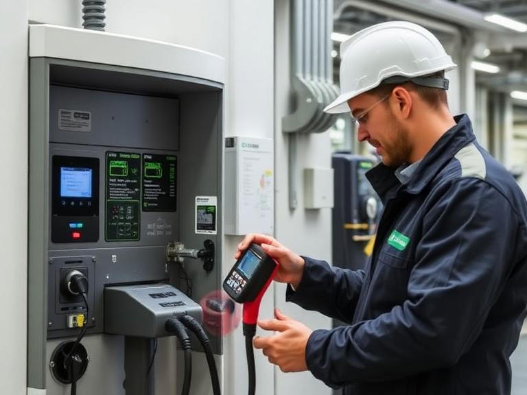
Frequently Asked Questions (FAQs)
1. What is the typical deployment cost for a public DC fast charging hub?
Deploying a multi-dispenser public DC fast charging (DCFC) hub with 150 kW to 350 kW output typically costs between $150,000 and $500,000+ per site. Total expenses depend on grid utility connection requirements, transformer step-down additions, directional trenching, concrete work, and local utility demand charges.
2. What is the difference between Destination and Highway Corridor public EV charging?
Destination charging uses Level 2 AC (7.2 kW – 19.2 kW) or compact DC (30 kW – 50 kW) units located where drivers park for several hours (retail centers, hotels, workplaces). Highway Corridor charging relies on ultra-fast DC fast chargers (150 kW – 350+ kW) designed to replenish batteries to 80% within 15 to 25 minutes for long-distance travel.
3. How do public EV charging station operators make money?
Charge Point Operators (CPOs) generate revenue via direct energy markup tariffs (per-kWh or time-based fees), dynamic parking idle penalties, paid subscription memberships, on-screen advertising displays, site-host retail partnerships, and carbon offset credit monetization.
4. What is OCPP and why is it mandatory for public EV charging stations?
The Open Charge Point Protocol (OCPP) is an open communication standard linking charging station hardware with network management software. OCPP prevents vendor lock-in, allowing station owners to switch network management software without replacing their physical charging stalls.
5. What electrical voltage and power supply are required for public DC fast chargers?
Public DC fast chargers require a 480V 3-phase AC power input, which internal rectifiers convert to high-voltage DC (200V to 1000V DC). Multi-port fast-charging sites generally require a dedicated medium-voltage step-down transformer provided by the local electric utility.
6. What charging connector standards are used in public EV charging stations?
North America and international regions primarily use the North American Charging Standard (NACS / SAE J3400) and CCS Combo 1 / CCS Combo 2. Multi-standard public sites deploy dual-gun dispensers or integrated mechanical adapters to support all incoming EV models.
7. What are utility demand charges and how do they affect profitability?
Demand charges are commercial electricity fees based on the highest peak power draw (in kW) recorded over a brief window (e.g., 15 minutes) during a billing cycle. Sudden power spikes from fast charging can trigger high demand charges, which operators manage using Battery Energy Storage Systems (BESS) and dynamic software throttling.
8. What uptime reliability standard is required for public EV charging infrastructure?
Modern regulatory frameworks, such as the US National Electric Vehicle Infrastructure (NEVI) guidelines, require public charging networks to maintain a minimum 97% operational uptime per dispenser, tracked continuously via real-time cloud telemetry.
9. How long does it take to deploy a public EV charging site from start to finish?
A public EV charging project generally takes 6 to 18 months. Physical installation takes only a few days, but feasibility studies, site leasing, municipal permitting, utility grid interconnection approvals, and transformer manufacturing account for most of the schedule.
10. How do public EV charging stations handle payments without mobile apps?
Public stations feature integrated PCI-compliant contactless point-of-sale (POS) card terminals, NFC tap-to-pay (Apple Pay/Google Pay), and ISO 15118 Plug & Charge capabilities, allowing drivers to pay directly without downloading dedicated apps.
11. What is ISO 15118 Plug & Charge technology?
ISO 15118 is an international standard that enables secure cryptographic communication between the vehicle and the charging station. When plugged in, the system automatically authenticates the vehicle, authorizes charging, and bills the driver’s stored payment method without requiring card swipes or app interactions.
12. What physical safety features are needed for public EV charging stations?
Public sites require protective steel bollards, bright canopy lighting, emergency power-off (EPO) cutoffs, clear sightlines, ADA-compliant accessibility aisles, break-away cable couplers, and active liquid cooling in high-amperage cables.
13. Can public EV charging stations operate with solar power and battery storage?
Yes. Integrating localized solar canopies and Battery Energy Storage Systems (BESS) allows public charging stations to buffer grid power draw, cut peak demand charges, deliver clean renewable energy, and continue operating during local power outages.
14. What grants and incentives exist to build public EV charging infrastructure?
Incentives include federal funding programs (such as NEVI in the United States), tax credits for alternative refueling property (30C), state air quality grants, municipal low-carbon fuel standard (LCFS) credit trading, and utility infrastructure rebate programs.
15. What is the difference between a Charge Point Operator (CPO) and an eMobility Service Provider (eMSP)?
A Charge Point Operator (CPO) manages, maintains, and operates physical charging hardware, grid connections, and hardware maintenance. An eMobility Service Provider (eMSP) handles customer-facing operations, providing driver apps, location mapping, billing accounts, and roaming connectivity.



Leave a Comment