
Table of Contents
Home EV Charger Repair Hyderabad: Complete Diagnostic, Hardware, and Field Engineering Protocol
An electric vehicle wallbox is an active power-delivery computer, not a static home appliance. Functioning under severe continuous thermal and electrical loads (drawing 32 Amps to 63 Amps continuously for 6 to 10 hours), residential AC chargers and DC micro-wallboxes in Hyderabad face intense operational degradation. High ambient summer temperatures (>42°C), severe grid-voltage transients, monsoonal ground-moisture fluctuations, and high-frequency relay switching cause mechanical, electronic, and firmware failures over time.
When a residential wallbox flashes red isolation error LEDs, repeatedly trips the main domestic Residual Current Device (RCD), fails to initiate the Control Pilot (CP) handshake with the vehicle, or locks the CCS2/Type-2 charging gun into the port, specialized field engineering is required. Attempting repair through standard local electricians who lack Electric Vehicle Supply Equipment (EVSE) diagnostic tools, high-voltage safety credentials, and oscilloscopes often leads to blown onboard chargers (OBC), severe neutral-burn faults, or voided hardware warranties.
This engineering manual covers fault diagnostics, board-level repair procedures, ground-fault resolution, cable-harness rebuilding, and utility compliance for professional home EV charger repair Hyderabad services.
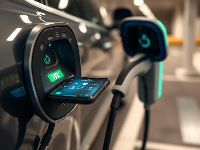
Anatomy of Home EVSE Failures: Root Cause Analysis
To systematically diagnose and repair home wallboxes, technicians analyze the hardware topology into three critical subsystems: High-Voltage Power Line, Low-Voltage Logic Controller, and Safety Grounding Subsystem.
                               ┌──────────────────────────────────────────────┐
                               │       EVSE FAILURE ANALYSIS TAXONOMY         │
                               └──────────────────────┬───────────────────────┘
                                                      │
         ┌────────────────────────────────────────────┼────────────────────────────────────────────┐
         │                                            │                                            │
┌────────┴───────────┐                       ┌────────┴───────────┐                       ┌────────┴───────────┐
│ High-Voltage Power │                       │ Low-Voltage Logic  │                       │ Safety Grounding   │
│ Line Subsystem     │                       │ & Pilot Subsystem  │                       │ Subsystem          │
└────────┬───────────┘                       └────────┬───────────┘                       └────────┬───────────┘
         │                                            │                                            │
         ├─ Contactor Contact Pitting                 ├─ Control Pilot (CP) Drift                  ├─ High Earth Impedance (>5Ω)
         ├─ Terminal Block Thermal Meltdown           ├─ Proximity Pilot (PP) Resistor Short       ├─ Neutral-to-Earth Potential (>5V)
         ├─ MOV / Surge Protector Explosion           ├─ Solenoid Gun Lock Jamming                 ├─ RDC-DD (6mA DC Sensor) Saturation
         └─ FRLS Cable Insulation Breakdown           └─ Microcontroller Firmware Corruption       └─ PE Line Corrosion & Continuity Loss
Diagnostic Matrix: Error Symptoms, Root Causes, and Field Action
When an AC home charger or small DC wallbox halts operation, visual LED indicators, display codes, and electrical measurements define the exact repair protocol required.
| Diagnostic Code / Error Symptom | Visual / Measurement Sign | Root Cause | Engineering Field Repair Action |
| PE Line Isolation Fault | Flashing Red LED / Code E01 | Protective Earth resistance > 5.0 Ohms or open earth line | Chemical earth pit re-hydration, secondary copper rod bonding, or neutral-earth link restoration. |
| Contactor Weld / Stiction | Solid Red LED / Code E04 | Main power switching relay contacts carbonized or welded shut | Desolder damaged relay from PCB or replace industrial 40A/63A AC contactor assembly. |
| Control Pilot (CP) Signal Failure | Yellow Warning / Session Stuck at “Preparing” | Diode short inside vehicle OBC port or CP line voltage drop | Oscilloscope analysis of 1.0 kHz PWM signal; CP line resistor/diode network replacement in gun assembly. |
| Over-Temperature Throttling | Orange Flashing LED / Current drops to 10A | Loose terminal block screw, degraded thermal paste, or ambient heat | Retorque terminal lug connections to spec; apply high-conductivity thermal paste; install canopy shade. |
| Ground Leakage / RCD Tripping | Instant tripping of Type-A/B breaker | AC/DC leakage current exceeding 30mA AC or 6mA DC | Megger insulation testing (1000V DC) on feeder cable; replacement of degraded 6mA DC sensor (RDC-DD). |
| Over/Under Voltage Fault | Red Warning / Code E02 or E03 | TGSPDCL grid line voltage drops <180V or surges >265V | Phase-selector switch installation, automatic line voltage stabilizer integration, or utility tap adjustment. |
| Guns Lock Mechanism Failure | Connector stuck in vehicle / Mechanical click absent | Actuator motor failure or loss of 12V pulse signal | Manual emergency mechanical release activation; replacement of gun internal solenoid locking motor. |
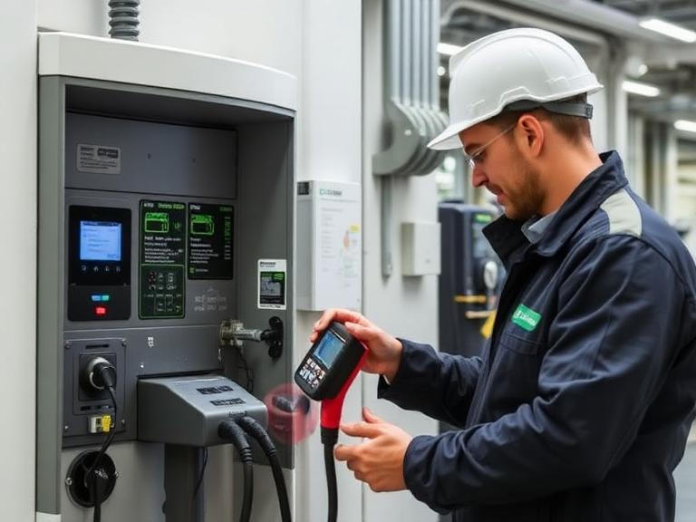
Technical Guide: Diagnostic and Board-Level Repair Procedures
┌────────────────────────────────────────────────────────────────────────────────────────┐
│                        FIELD REPAIR ENGINEERING WORKFLOW                               │
└───────────────────────────┬────────────────────────────────────────────────────────────┘
                                │
  Step 1: Isolation & Electrical Safe-Off ─┼──> Lockout/Tagout (LOTO) & Multimeter Zero-Verification
                                │
  Step 2: Signal Analysis & Emulation ─────┼──> Oscilloscope Measurement of CP PWM (12V -> 9V -> 6V)
                                │
  Step 3: Insulation Megger Testing ───────┼──> Apply 1000V DC Test across L1/L2/L3/N to Earth
                                │
  Step 4: Component Board-Level Replacement ┼─> Replace Welded Contactors, SPDs, or Logic Power Modules
                                │
  Step 5: Full Load Validation Cycle ──────┼──> Perform 32A Continuous Charge Test with Thermal Imaging
Protocol 1: Resolving Ground Failures and PE Isolation Faults
Hyderabad’s rocky terrain causes significant ground resistance fluctuations. When a wallbox reports a PE fault, field engineers execute the following repair steps:
- Earth-to-Neutral Potential Check: Using a calibrated Digital Multimeter (DMM), measure the voltage between Neutral (N) and Protective Earth (PE) at the charger inlet terminals under zero load and full load. If $V_{N-PE} > 5.0\text{V}$, the neutral wire is overloaded, floating, or experiencing excessive voltage drop upstream.
- Earth Resistance Verification: A 3-point fall-of-potential test using an Earth Ground Resistance Tester measures earth pit impedance. If reading exceeds $1.0\,\Omega$, engineers treat the chemical ground pit with ionic conductive compounds (graphite/bentonite) or sink an auxiliary 3-meter copper-bonded ground rod connected in parallel.
- PE Isolation Circuit Diagnostics: If ground resistance reads lower than $1.0\,\Omega$ but the charger still throws an error, the internal optocoupler/resistor ladder circuit on the PCB sensing earth continuity has failed due to a voltage spike. Engineers desolder damaged sensing resistors and swap internal optocouplers.
                                  ┌──────────────────────────────────────────┐
                                  │   GROUND RESISTANCE REPAIR DECISION TEE  │
                                  └────────────────────┬─────────────────────┘
                                                       │
                                        Measure N-PE Voltage & Earth Pit Ω
                                                       │
                           ┌───────────────────────────┴───────────────────────────┐
                           │                                                       │
               If VN-PE > 5.0V or Ω > 1.0                               If VN-PE < 5.0V & Ω < 1.0
                           │                                                       │
              ┌────────────┴────────────┐                             ┌────────────┴────────────┐
              │ Ground System Failure   │                             │ Wallbox Sensor Fault    │
              └────────────┬────────────┘                             └────────────┬────────────┘
                           │                                                       │
     • Treat pit with conductive chemical matrix                 • Inspect PCB earth sensing optocoupler
     • Drive secondary parallel earth rod                        • Swap sensing ladder resistors on logic board
     • Tighten floating upstream neutral lugs                    • Re-calibrate internal grounding threshold
Protocol 2: Cable Harness and CCS2/Type-2 Gun Reconstruction
The charging cable experiences heavy physical abuse, pin oxidation, and strain at the handle entry point.
┌────────────────────────────────────────────────────────────────────────────────────────┐
│                        TYPE-2 / CCS2 CABLE REPAIR TOPOLOGY                             │
└───────────────────────────┬────────────────────────────────────────────────────────────┘
                                │
  Control Pilot (CP) Line ──────┼──> Transmits 1.0 kHz PWM Signal for Current Capacity
                                │
  Proximity Pilot (PP) Line ────┼──> Detects Connection State & Resistor Value (e.g., 220Ω for 32A)
                                │
  Power Conductors (L1/N/PE) ───┼──> Silver-Plated Copper Lugs Torqued to Terminal Block
- Pin Oxidation & Resistance Thermal Runaway: Silver-plated copper pins inside the Type-2/CCS2 connector oxidize when exposed to rain or dust, leading to higher contact resistance ($R_{contact} > 100\text{ m}\Omega$). Under a 32A continuous current, power dissipation at the pin spikes according to Joule’s Law:$$P_{loss} = I^2 \times R_{contact}$$$$P_{loss} = (32)^2 \times 0.1 = 102.4\text{ Watts}$$This extreme localized heat melts the plastic housing. Repair engineers cut back damaged cable sections, strip conductors to exact tolerances, attach new silver-plated terminal pins, and cold-weld them using hydraulic hex-crimping tools.
- Proximity Pilot (PP) Resistor Repair: If the wallbox fails to detect connector insertion, the PP coding resistor inside the gun handle has failed or shorted. Technicians dismantle the handle assembly, replace the internal micro-switch, and install a precision metal film resistor ($220\,\Omega$ for 32A rating; $680\,\Omega$ for 16A rating) between the PP and PE contacts.
Local Grid Challenges in Hyderabad and Protective Solutions
Residential wallbox repair in HMDA neighborhoods often traces back to upstream grid distribution anomalies managed by TGSPDCL (Telangana State Power Distribution Company Limited).
┌────────────────────────────────────────────────────────────────────────────────────────┐
│                        HYDERABAD GRID VOLTAGE ANOMALIES                                │
└───────────────────────────┬────────────────────────────────────────────────────────────┘
                                │
  Phase Swells (>270V AC) ──────┼──> Blows Input Metal Oxide Varistors (MOVs) & SPDs
                                │
  Phase Sag / Brownouts (<170V) ┼──> Forces Contactor Chatter, Pitting, and Thermal Failure
                                │
  Lightning / Switching Surges ─┼──> Destroys Internal 12V DC Logic Power Supplies
- Voltage Swells and Neutral Shift in High-Density Residential Areas: In areas like Kukatpally, Kondapur, and Manikonda, rapid residential development often leads to asymmetric phase loading on local distribution transformers. Neutral drift can push single-phase terminal voltage from 230V up to 275V AC. High voltage triggers over-voltage protection or explodes primary Metal Oxide Varistors (MOVs) on the charger mainboard.
- Contactor “Chattering” Due to Low Voltage Sags: During summer peak load periods, incoming supply voltage can drop below 170V. Under-voltage causes internal 12V/24V solenoid contactors to rapidly cycle on and off (“chattering”). This high-frequency arcing pits contact surfaces and welds power contact points shut.
                                  ┌──────────────────────────────────────────┐
                                  │    GRID ANOMALY RECTIFICATION ROADMAP    │
                                  └────────────────────┬─────────────────────┘
                                                       │
                                          Diagnose Ingress Grid Voltages
                                                       │
                           ┌───────────────────────────┴───────────────────────────┐
                           │                                                       │
              Volts > 265V or < 180V                                    Transient Voltage Spikes
                           │                                                       │
              ┌────────────┴────────────┐                             ┌────────────┴────────────┐
              │ Voltage Regulation      │                             │ Transient Suppression   │
              └────────────┬────────────┘                             └────────────┬────────────┘
                           │                                                       │
     • Install heavy-duty servo motor stabilizer                 • Replace blown Type 2 Surge Arrestors (SPD)
     • Fit auto-cut-off over/under voltage relay                 • Replace secondary MOVs on internal PCB
     • Balance domestic distribution panel loads                 • Upgrade sub-panel lightning protection
Cost Breakdown: Home EV Charger Diagnostics and Component Repair
Homeowners save significant expense by repairing component-level faults rather than replacing the entire wallbox assembly.
┌────────────────────────────────────────────────────────────────────────────────────────┐
│                        REPAIR COST DISTRIBUTION ANALYSIS                               │
└───────────────────────────┬────────────────────────────────────────────────────────────┘
                                │
  Doorstep Inspection & Oscilloscope Diagnostics ───┼──> ₹1,200 – ₹1,800
                                │
  Heavy-Duty Contactor / Relay Replacement ─────────┼──> ₹2,800 – ₹4,800
                                │
  CCS2 / Type-2 Cable Harness & Gun Swap ───────────┼──> ₹6,500 – ₹11,500
                                │
  Board-Level PCB / Microcontroller Repair ─────────┼──> ₹3,500 – ₹6,800
                                │
  Chemical Earth Pit & Ground Line Overhaul ────────┼──> ₹5,500 – ₹8,500
Note: Component repairs typically include a comprehensive 90-day to 12-month field service warranty covering parts and labor.
Preventive Engineering & Maintenance Protocols
Implementing proactive preventive maintenance reduces emergency breakdowns, extends wallbox operational lifespan, and protects the electric vehicle’s onboard battery system.
┌────────────────────────────────────────────────────────────────────────────────────────┐
│                      PREVENTIVE MAINTENANCE SERVICE PROTOCOL                           │
└───────────────────────────┬────────────────────────────────────────────────────────────┘
                                │
  Terminal Torque Verification ─┼──> Check L1/L2/L3/N Screw Tightness with Calibrated Torque Wrench
                                │
  Insulation Breakdown Check ───┼──> Apply 1000V Megger Test Across All HV Conductors to Earth
                                │
  Earth Pit Ionic Hydration ────┼──> Flush Pit with Chemical Moisture Matrix & Measure Ω
                                │
  Thermal Imaging Inspection ───┼──> Run Infrared Camera Scan Under Full 32A Load Cycle
- Bi-Annual Terminal Torque Check: Thermal cycling causes screw terminals to loosen gradually over time. Technicians use insulated torque screwdrivers to re-torque terminal block screws to manufacturer specifications (typically $2.5\text{ Nm}$ to $3.5\text{ Nm}$), preventing terminal meltdown.
- Infrared Thermal Inspection: Operating the charger at a continuous 32A load for 20 minutes while scanning internal components with an infrared thermal camera highlights hot spots before catastrophic failure occurs.
- Moisture & Pest Proofing: In humid or monsoon conditions, geckos, ants, and moisture enter wallbox enclosures through unsealed cable glands. Field servicing includes renewing silicone gland seals, adding IP65 gaskets, and applying dielectric protective coatings to printed circuit boards.
Frequently Asked Questions (FAQs)
1. Why is my home EV charger showing a red indicator light and refusing to start charging?
A continuous or flashing red light usually signifies a critical safety fault condition—most commonly a Protective Earth (PE) isolation error, neutral-to-earth voltage imbalance exceeding 5V, internal relay contactor weld, or over-temperature sensing inside the terminal block.
2. How quickly can a field technician respond to an emergency home EV charger breakdown in Hyderabad?
Emergency field engineering response units arrive on-site within 2 to 4 hours across major Hyderabad hubs including Gachibowli, HITEC City, Kondapur, Jubilee Hills, Nallagandla, and Financial District, equipped with mobile diagnostic tools and critical replacement components.
3. What causes the home EV charger to trip the main house circuit breaker or RCD as soon as I plug in the car?
Instant breaker tripping is caused by high-voltage AC or DC earth leakage (>30mA AC / >6mA DC) resulting from damaged cable insulation, moisture ingress in the connector head, shorted internal varistors, or an underrated Type-A RCD reacting to smooth DC leakage generated by the vehicle OBC.
4. Can a damaged Type-2 or CCS2 charging gun cable be repaired or replaced independently without buying a new wallbox?
Yes. Worn charging pins, broken locking latches, cut cable jackets, or faulty Control Pilot signal lines can be repaired by re-terminating the harness or replacing the entire gun assembly while keeping your original wallbox logic unit intact.
5. Why is my home charger taking twice as long to charge my EV compared to before?
Thermal power throttling is the main cause. If terminal block connections loosen or ambient temperatures spike, internal thermistors force the CPU to throttle current from 32A down to 16A or 10A to prevent thermal runaway.
6. What causes an EV charging connector gun to become physically stuck inside the car’s charging port?
Guns lock up when the electronic solenoid pin actuator fails to retract due to loss of the 12V lock/unlock pulse, physical misalignment from dropped connector heads, or a frozen Control Pilot handshake protocol.
7. How do summer heatwaves in Hyderabad affect home EV charger internal electronics?
Direct sun exposure and high outdoor ambient temperatures (>42°C) trigger over-temperature protection mode, age electrolytic capacitors on power supply boards prematurely, and dry out thermal interface paste on internal power switching MOSFETs.
8. Why does my EV display an “Incompatible Power Supply” or “Grid Quality Failure” warning during home charging?
This warning occurs when the incoming supply voltage drops below 190V under 32A load, exceeds 260V due to local transformer imbalance, or when the line frequency fluctuates beyond the strict limits required by vehicle safety firmware.
9. Are spare parts available for international imported EV wallboxes installed in Hyderabad homes?
Yes. Certified EVSE field engineering services carry universal replacement components including heavy-duty 40A/63A AC contactors, 12V DC switching power supplies, Type-B differential current sensors, control transformers, and standardized Type-2/CCS2 cable harnesses.
10. How do technicians fix a high earth resistance fault on a home EV charger in rocky areas like Jubilee Hills or Manikonda?
Technicians re-engineer the grounding line by installing a secondary chemical earth pit with bentonite/graphite compounds or installing dual copper-bonded earth rods connected in parallel to achieve resistance below 1.0 Ohm.
11. Can a lightning strike or grid surge destroy a home EV charger, and can it be repaired?
Grid surges blow out the primary Surge Protection Device (SPD), metal oxide varistors (MOVs), and input fuses in the sub-panel. Technicians can restore the charger by replacing burnt SPDs, input protection boards, and corrupted flash microcontrollers.
12. How do I know if an EV charging issue is caused by the wallbox or my electric vehicle’s internal OBC?
Field technicians use an EVSE handheld simulator to test the wallbox independently under full electrical load. If the wallbox generates valid Control Pilot PWM signals and latches its contactor properly into a test load, the issue lies within the vehicle OBC or port.
13. What is the warranty coverage provided on doorstep home EV charger repair services?
Repairs performed by certified field engineers include a 90-day to 12-month service warranty on newly installed replacement parts (such as contactors, mainboards, SPDs, and cable guns) along with field labor guarantees.
14. Is it safe to reset the main EV sub-panel breaker repeatedly when the charger trips?
No. Repeatedly resetting a breaker against an active ground fault or short circuit causes extreme arc flashing inside terminal blocks, damages vehicle sensitive electronics, and risks permanent insulation breakdown.
15. What preventive maintenance steps can prevent sudden home EV wallbox breakdowns in Hyderabad?
Bi-annual maintenance should include checking terminal torque tightness, Megger insulation testing of underground feeder cables, re-watering chemical earth pits before summer, inspecting gun pins for carbonization, and updating unit firmware.
Leave a Reply